Alpha, the circuit is neither a series nor a parallel circuit. It is a combination, or compound circuit. In other words, some of the components are arranged in series with respect to other components, and some are arranged in parallel. You keep insisting that, for example, all of the parallel components must have the same voltage. This is only true for a purely parallel circuit, but not when there are series components mixed in with the parallel components. Here, have a little read about combination circuits and learn something.
When analyzing combination circuits, it is critically important to have a solid understanding of the concepts that pertain to both series circuits and parallel circuits. Since both types of connections are used in combination circuits, the concepts associated with both types of circuits apply to the respective parts of the circuit.
Since you're fond of quoting out of context, let's see what the section that paragraph came from
really says:
Previously in Lesson 4, it was mentioned that there are two different ways to connect two or more electrical devices together in a circuit. They can be connected by means of series connections or by means of parallel connections. When all the devices in a circuit are connected by series connections, then the circuit is referred to as a series circuit. When all the devices in a circuit are connected by parallel connections, then the circuit is referred to as a parallel circuit. A third type of circuit involves the dual use of series and parallel connections in a circuit; such circuits are referred to as compound circuits or combination circuits. The circuit depicted [below] is an example of the use of both series and parallel connections within the same circuit. In this case, light bulbs A and B are connected by parallel connections and light bulbs C and D are connected by series connections. This is an example of a combination circuit.
When analyzing combination circuits, it is critically important to have a solid understanding of the concepts that pertain to both series circuits and parallel circuits. Since both types of connections are used in combination circuits, the concepts associated with both types of circuits apply to the respective parts of the circuit. The main concepts associated with series and parallel circuits are organized in the [tables] below.
Series Circuits
- The current is the same in every resistor; this current is equal to that in the battery.
- The sum of the voltage drops across the individual resistors is equal to the voltage rating of the battery.
- The overall resistance of the collection of resistors is equal to the sum of the individual resistance values,
Rtot = R1 + R2 + R3 + ...
Parallel Circuits
- The voltage drop is the same across each parallel branch.
- The sum of the current in each individual branch is equal to the current outside the branches.
- The equivalent or overall resistance of the collection of resistors is given by the equation
1/Req = 1/R1 + 1/R2 + 1/R3 ...
Can you point to
any two components that are in series in
the filter circuit we're discussing, using the
correct definition for series circuit? The one from the reference
you cited will suffice. Note the first concept in the
Series Circuit table, with
bolding added.
"You keep insisting that, for example, all of the parallel components must have the same voltage."
It's not just me. See the
references cited in
my previous response, or, even better, it's in
bold in the Parallel Circuits table from the reference
you provided.
By the way, I searched the page
you cite for the word "pure" as in "pure serial circuit" and "pure parallel circuit" or "purely parallel circuit" and came up empty. They talk about serial circuits and parallel circuits without further qualification, and define them exactly as I (and everyone else I've read except you) do.
As Rayzor already mentioned, the filter circuit in question is a type of Chebyshev PI filter, which is a combination circuit, because some of the components are in series and some are in parallel. Here is the definition for a basic PI filter. The definition is the circuit in its most basic form, and the filter in question has extra components added, but it is the same circuit none the less.
A PI filter is a filter that has a series element and two parallel elements connected in the shape of the Greek letter PI.
That's a rather informal description of the PI circuit. Not everything published on the Internet is strictly correct; if what you're reading matters, cross-checking against other
reliable sources is prudent.
Here is an expanded version of the PI filter. You will notice that this example only has the series component on one leg of the input.
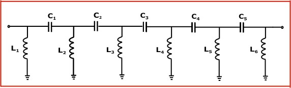
There are no series components according to the definition of a series circuit. This is easy to show:
Assuming the signal source is on the left and load is on the right, and inductors L
1, L
2, and L
3 and capacitors C
1 and C
2 in the circuit above all have finite, non-zero impedance, then
some of the current that passes through C
1 will pass through L
2 and
the remainder will pass through C
2. Remember,
The current is the same in every [element] (from
your reference). Since the current through C
1 and C
2 are not equal, they cannot be in series. Note that C
1 and L
2 aren't a series circuit, either, because their currents are
also different.
Similarly, the inductors are not in parallel because the voltage at the node between C
1 and C
2 must be lower than the signal voltage because of the voltage drop due to the current through the impedance of C
1 (Ohm's Law and all that). Ergo, the voltage across L
2 is less than the voltage across L
1 and the characteristic
that the voltage drop is the same across each parallel branch (from
your reference) fails.
You claim that the capacitors on the positive side of the input are not in series with the ones in the negative side.
Given the necessary characteristic of a series circuit from
your reference[nb]I keep harping on this because you seem to ignore
my references. Maybe you'll be willing to learn from your own.[/nb] that
the current is the same in every resistor, go back and review the
analysis provided by BJ1234 a few days ago shows a different current through each capacitor. Since this characteristic is absent, the capacitors are not in series. Period. This should not be that hard to understand.
Note that that current through each element being equal is a necessary, but not sufficient, requirement to determine that elements are in series. Since that requirement isn't met, however, the elements are categorically
not in series.
<Snarky ad-hom .> Here is an example of a circuit that has resistors in the positive and negative side, as well as in between. Please, do a little bit of studying before you show any more of your ignorance.
Image of circuit with resistors in series with battery.
I think all would agree that that's an example of a series circuit. Do you have a point?
I only have a bachelor's electrical degree, but I do have a friend who has a masters in EE, has a PE certification, and is only a dissertation away from his doctorate, from what I remember him telling me in the past. If you want, I can have him send me an email confirming what I have said and either post it here with his name and email blocked out, or forward it directly to you without blocking his name or email, if you don't mind giving me your email address.
Please do. Just post the correspondence here with the ID redacted. I don't want to pester your friend, and doubt he wants to be "investigated" by some member of the Flat Earth Society forums. There would be no practical way to truly verify what you claim he says is really from who you say he is without a meeting in person or, perhaps, involving other parties, and I don't intend to do that.
If possible, can he include reference(s) to scholarly or professional publication(s), or college textbook(s) that support what you are saying; that would be better than giving me a name and email address.